Your thermoelectric cooler isn’t reaching the sub-zero temperatures you need, and simply cranking up the power isn’t solving the problem. This frustrating reality affects DIY enthusiasts, lab technicians, and engineers alike—most Peltier-based systems plateau at just 20-30°C below ambient temperature when they’re capable of much more. The secret to achieving truly cold temperatures lies not in brute force power application but in a systematic approach that addresses the entire thermal chain. By optimizing heat rejection, refining thermal interfaces, implementing precision control, and applying strategic insulation, you can push your thermoelectric cooler to achieve temperatures 50-70°C below ambient—sometimes even lower. This guide reveals the exact methods professional engineers use to maximize thermoelectric cooler performance.
Upgrade Your Hot Side Cooling System Immediately
The most overlooked factor in thermoelectric cooling performance is inadequate hot side management. Your TEC can only create a temperature differential—typically 30-70°C depending on the model—so if your hot side runs at 50°C, your cold side can never drop below -20°C even with perfect conditions.
Replace Stock Cooling with High-Performance Solutions
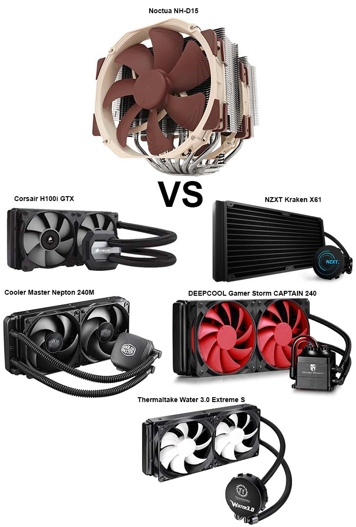
Ditch the small 40mm fans that came with your cooler—they’re completely inadequate for serious cooling applications. Install a high-CFM CPU cooler like the Noctua NH-D15 with its dual-tower heatsink design that provides 3-5× better thermal performance than stock solutions. For extreme cooling, implement a custom water loop featuring a copper microchannel cold plate directly bonded to the TEC’s hot side, coupled with a 360mm radiator running in push-pull fan configuration. This setup maintains the hot side within 5-10°C of ambient temperature, dramatically improving your cold side performance.
Implement Multi-Stage Hot Side Cooling
For the most demanding applications, consider a staged hot side cooling approach:
– Primary cooling: High-flow DDC pump circulating coolant through microchannel cold plate
– Secondary cooling: Dedicated Peltier module actively cooling the primary coolant loop
– Tertiary cooling: Phase change materials absorbing thermal spikes during load changes
This layered approach keeps your hot side remarkably stable even when ambient temperatures fluctuate, allowing your cold side to maintain consistently lower temperatures.
Optimize Thermal Interfaces and Mounting Pressure

Even the best cooling system fails with poor thermal interfaces—each microscopic air gap creates thermal resistance that sabotages your temperature goals. Professional systems achieve maximum performance through meticulous attention to interface quality and mounting technique.
Apply Premium Thermal Interface Materials Strategically
Skip standard thermal paste for critical TEC applications. Instead, use Thermal Grizzly Kryonaut (8.5 W/mK) for standard operations or phase change materials like Honeywell PTM 7950 for permanent installations. For ultimate performance on nickel-plated surfaces, apply liquid metal compounds—but only after verifying compatibility with your materials to prevent corrosion. Always apply interfaces in a thin, even layer (0.05-0.1mm) using the “pea-sized drop” method spread with a credit card for uniform coverage.
Achieve Perfect Mounting Pressure
TEC modules require precise mounting pressure—too little creates air gaps, while too much cracks the ceramic substrate. Use a torque screwdriver set to 2.5-3.5 in-lb (varies by TEC size) and tighten mounting screws in a star pattern in three incremental passes. Insert a 0.5mm copper shim between the TEC and cold plate to distribute pressure evenly and improve heat spreading. This seemingly minor step can improve thermal transfer by 15-20% in properly executed systems.
Implement Precision Power Control Systems
Randomly applying maximum voltage to your TEC actually reduces cooling performance—thermoelectric modules operate most efficiently at specific voltage/current points that vary with the temperature differential.
Select the Optimal Power Delivery Method
Replace basic linear power supplies with MOSFET-based PWM controllers that deliver precise power without the heat generation of linear regulation. For stable temperature maintenance, implement a PID controller (like those based on Arduino platforms) that automatically adjusts power to maintain your target temperature within ±0.1°C. This prevents the “thermal overshoot” that occurs with simple on/off controllers and keeps your TEC operating at peak efficiency.
Match Power Supply to Your TEC Specifications
Using a power supply that doesn’t match your TEC’s requirements wastes energy and limits performance. For a standard 12706 TEC (12V, 6A), select a Meanwell LRS-100-12 power supply that provides clean 12V power with 8A capacity—sufficient for startup current spikes. For multi-TEC systems, calculate total current requirements (TEC current × number of modules × 1.5 safety factor) and select an 80+ Gold or Platinum rated server power supply for maximum efficiency (90%+ vs 85% for standard units).
Apply Advanced Insulation Techniques to Prevent Heat Ingress

Your cooling system works against a constant battle with ambient heat—without proper insulation, you’re fighting an uphill battle that wastes 50% or more of your cooling capacity.
Install Vacuum Insulation Panels Around Cold Zones
Standard foam insulation simply can’t compete with vacuum insulated panels (VIPs) that provide R-50+ insulation value in minimal space—5-10× better than conventional foam. Install VIPs around your cold chamber, paying special attention to corners and seams where thermal bridging occurs. For DIY applications, cut VIPs to size using a utility knife and seal edges with aluminum tape to maintain vacuum integrity.
Create a Multi-Layer Insulation Barrier
For ultra-low temperature applications, implement a multi-layer approach:
1. Inner layer: Closed-cell foam to prevent moisture ingress
2. Middle layer: Aluminum foil tape to block radiant heat
3. Outer layer: Vacuum insulation panel for maximum thermal resistance
4. Final seal: Dielectric grease on all electrical connections to prevent condensation
This comprehensive insulation strategy reduces heat infiltration by 70-80% compared to basic foam insulation, allowing your cold side to reach significantly lower temperatures.
Implement Multi-Stage Cooling for Extreme Temperature Drops
When single-stage TECs reach their limits (typically -30 to -40°C), you need a cascade approach to achieve even colder temperatures.
Build an Effective Two-Stage Cooling System
Mount a secondary TEC module on the cold side of your primary cooling stage:
– Stage 1: High-power TEC (12710 or 12714) cools to 0°C
– Stage 2: Medium-power TEC (12706) cools primary cold side to -30°C
– Critical interface: Use thermal epoxy between stages for maximum transfer
This configuration requires careful thermal isolation between stages but can achieve temperatures as low as -50°C—far beyond what single-stage systems can accomplish. Power the secondary stage with a separate, lower-amperage supply since it handles less heat load.
Prevent Condensation Damage in Sub-Zero Systems
When cooling below the dew point, moisture becomes your enemy. Apply silicone conformal coating to all electronics on the cold side and seal connections with dielectric grease. Install a secondary “guard” TEC around critical components that maintains temperatures just above dew point to prevent condensation from forming on sensitive electronics—a technique used in professional PCR machines and medical refrigeration systems.
Final Performance Optimization Checklist
To maximize your thermoelectric cooler’s cold performance, implement these critical steps:
- Hot side temperature: Keep within 5-10°C of ambient (measure with thermocouple)
- Thermal interfaces: Refresh every 6 months and verify even contact
- Power delivery: Use PID control rather than maximum voltage
- Insulation: Apply vacuum panels with sealed seams
- Mounting pressure: Verify with torque wrench during installation
- Condensation control: Implement conformal coating below dew point
The difference between a mediocre thermoelectric cooler and one that achieves genuinely cold temperatures lies in this systematic approach to the entire thermal chain. By optimizing hot side cooling, perfecting thermal interfaces, implementing precision power control, and applying advanced insulation techniques, you transform your system from merely “cool” to genuinely cold. Remember that thermoelectric cooling is a balancing act—you’re not just making something cold, but creating and maintaining a temperature differential against constant thermal pressure from the environment. Implement these techniques methodically, measure your results at each stage, and you’ll consistently achieve the coldest possible temperatures from your thermoelectric cooling system. For ongoing performance, schedule quarterly maintenance to refresh thermal interfaces and verify insulation integrity—this simple habit maintains peak cooling performance for years.