You’re in a dairy processing plant watching milk flow through stainless steel pipes. Suddenly, the liquid needs rapid cooling after pasteurization—but how does this happen without wasting energy? The answer lies in the unassuming plate cooler humming quietly in the corner. How does a plate cooler work to achieve this critical temperature control? This compact device silently transfers heat between two fluids with remarkable efficiency, often cutting energy costs by 30% compared to older systems. Whether you’re troubleshooting an industrial cooling system or designing a new HVAC setup, understanding this technology is essential. In this guide, you’ll discover exactly how plate coolers transfer heat through corrugated plates, why counter-current flow maximizes efficiency, and what makes them indispensable across industries from food processing to marine engineering.
Plate coolers solve a fundamental engineering challenge: moving thermal energy between fluids without mixing them. Unlike bulky shell-and-tube exchangers, these units achieve superior heat transfer in a fraction of the space. The secret lies in their precision-engineered internal architecture and fluid dynamics. By the end of this guide, you’ll recognize common failure points, understand maintenance requirements, and appreciate why 85% of new industrial cooling installations now specify plate heat exchangers. Let’s dissect exactly how this workhorse technology operates.
Plate Cooler Anatomy: Components and Functions
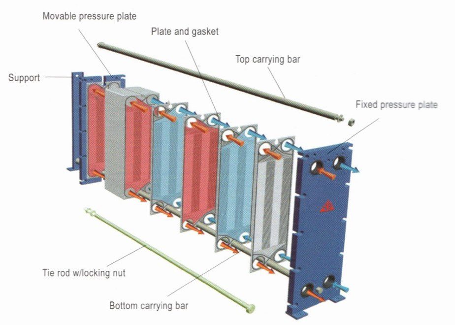
Every plate cooler’s performance hinges on four critical components working in concert. When you inspect an open unit, these elements reveal why this design dominates modern thermal management.
Plate Cooler Components
The stainless steel or titanium plates form the exchanger’s beating heart. These aren’t flat sheets but precision-engineered corrugated surfaces only 0.4-0.8mm thick—thinner than a credit card. Arranged in a compressed stack called the plate pack, they create narrow channels just 2-5mm wide between each plate. This tight spacing maximizes surface area contact with fluids while minimizing material use.
Elastomer gaskets made from EPDM or Viton seal these plates together. Unlike simple O-rings, these gaskets feature intricate molded channels that route fluids through alternating pathways. They’re the unsung heroes preventing catastrophic cross-contamination—imagine milk mixing with cooling water in a dairy plant. The heavy-duty steel frame with long tightening bolts applies 50-100 tons of clamping force to compress the entire assembly. Proper torque on these bolts (typically 25-40 Nm) is non-negotiable; under-tightening causes leaks while over-tightening cracks plates. Finally, inlet/outlet ports on the frame head direct hot and cold fluids into their designated channels, with port size directly impacting pressure drop.
The Role of Corrugated Plates
Those distinctive ridges and valleys on each plate aren’t decorative—they’re thermal turbochargers. The chevron pattern forces fluids into turbulent flow, shattering the insulating boundary layer that forms on smooth surfaces. Without this turbulence, heat transfer efficiency would drop by 60-70%.
This design achieves three critical functions simultaneously: First, it increases structural rigidity so ultra-thin plates withstand 25+ bar pressure. Second, it creates constant fluid agitation that prevents particle settling—crucial when handling milk or chemical slurries. Third, it multiplies effective surface area by 3-5x compared to flat plates. The sharper the chevron angle (typically 30°-65°), the higher the turbulence and heat transfer rate—but also the greater the pressure drop. Engineers optimize this angle based on your specific fluid viscosity and required flow rates.
Gasket Function and Sealing
Gaskets perform two life-or-death functions that most operators overlook. They isolate hot and cold fluid streams by creating labyrinthine flow paths: Hot fluid enters port A, snakes through channels between plates 1-2 and 3-4, then exits at port B. Simultaneously, cold fluid flows through channels 2-3 and 4-5 via ports C and D. The gasket pattern physically blocks crossover between these paths.
More importantly, gaskets incorporate engineered failure points. Made from softer material than the plates, they’ll leak externally before allowing fluid mixing—a critical safety feature in pharmaceutical or food applications. During maintenance, inspect gaskets for compression set (permanent flattening) or chemical swelling. A single compromised gasket can reduce efficiency by 40%, so replace them every 3-5 years depending on operating temperatures.
How Does a Plate Cooler Work? The Counter-Current Flow Principle

The real magic happens when fluids start moving. How does a plate cooler work to achieve 90%+ thermal efficiency? It’s all about the dance between hot and cold streams.
Counter-Current Flow Pattern
Picture hot process fluid entering the top port while cooling water enters the bottom port—flowing in opposite directions through adjacent channels. This counter-current arrangement maintains a near-constant temperature differential across the entire plate length. Where the hottest fluid meets the coldest coolant, maximum heat transfer occurs. As both fluids progress, the temperature gap remains optimal rather than collapsing like in parallel-flow designs.
This configuration allows plate coolers to achieve “temperature cross”—where the cold fluid outlet temperature actually exceeds the hot fluid outlet temperature. Shell-and-tube exchangers can’t do this, making plate units 30-50% more efficient for the same duty. In a dairy pasteurizer, this means cooling 95°C milk to 4°C using 1°C river water—a feat impossible with older technology.
Heat Transfer Through the Plates
The thermal handshake happens across those razor-thin metal barriers. As hot fluid flows down one channel, heat energy vibrates through the stainless steel plate (conductivity: 15-20 W/m·K) into the cooler fluid on the other side. The 0.5mm plate thickness minimizes conductive resistance, while turbulence ensures fresh fluid constantly contacts the surface.
Key physics at play: The Nusselt number (heat transfer coefficient) jumps from 100-300 in laminar flow to 3,000-8,000 in turbulent plate flow. This means heat moves 30-80x faster than through a smooth pipe. In practical terms, a single-pass plate cooler can transfer 1MW of heat in a unit smaller than a dishwasher—something that would require a 10-foot-long shell-and-tube exchanger.
Sealing and Channel Management
Gasket geometry creates an invisible maze directing fluids. Notice the double-seal gasket design around ports: One seal blocks fluid from leaking externally, while an inner seal prevents channel crossover. During assembly, plates rotate 180° alternately so port openings align only with every other channel.
When tightening the frame, plate alignment pins ensure perfect channel registration. Misalignment by just 2mm creates dead zones where fluid bypasses turbulence, reducing efficiency by 15-20%. Always verify plate numbering during reassembly—reversing a single plate can block 50% of flow paths. This precision engineering enables the zero-mixing guarantee that makes plate coolers FDA-compliant for food processing.
Applications and Operational Considerations
Plate coolers shine where space, efficiency, or hygiene are critical—but they’re not universal solutions. Know where they excel and where limitations apply.
Common Industrial Applications
In dairy processing, plate coolers pasteurize 20,000 liters/hour of milk while recovering 95% of thermal energy—a $50,000/year energy saving. Marine engineers rely on them to cool engine lube oil in tight engine rooms, where their modular design allows adding plates during refits. Pharmaceutical plants use sanitary titanium units for sterile fluid heating, leveraging the easy-open design for validation swabbing. Even data centers now deploy them in free-cooling systems, using cold river water to chill server racks without running chillers 6-8 months yearly.
Critical success factor: Match plate material to your fluid. Use 316L stainless for food/beverages, titanium for seawater or chlorine, and Hastelloy for aggressive acids. A chemical plant learned this the hard way when 304 stainless plates corroded in nitric acid service—replacing them with titanium cost $12,000 but prevented $200,000 in downtime.
Efficiency and Turbulence

The Reynolds number (flow regime indicator) reveals why plate coolers outperform competitors. At Re>200, turbulence begins; plate exchangers operate at Re=5,000-20,000 versus Re=2,000-5,000 in shell-and-tube units. This intense mixing eliminates the stagnant boundary layer responsible for 70% of thermal resistance.
But turbulence has trade-offs: Higher flow rates increase pressure drop by 4-8x compared to smooth pipes. If your pump runs hot after installing a plate cooler, check if you’ve exceeded the recommended 0.5-1.0 bar pressure drop per side. A simple fix: Increase the chevron angle (e.g., from 30° to 60°) to reduce channel velocity while maintaining turbulence.
Maintenance and Fouling Resistance
Here’s why operators love plate coolers: Open the frame, slide out the plate pack, and you’ve got instant access for inspection. Fouling—the buildup of scale or particles—is minimized by turbulence but still occurs with hard water or viscous fluids. When it does, simply:
- Loosen bolts to 50% compression (never fully release)
- Slide plate pack into a cleaning tank
- Soak in 5% citric acid for mineral scale or alkaline detergent for organic deposits
- Rinse with high-pressure water (<50 bar to avoid denting plates)
Unlike shell-and-tube exchangers requiring rod cleaning, this takes 2 hours versus 2 days. Pro tip: Install strainers upstream—particles over 2mm cause 80% of fouling issues. In a brewery case study, adding a 1mm strainer doubled the time between cleanings from 3 to 6 months.
Final Note: Understanding how a plate cooler work transforms you from a passive user to an informed operator. These units achieve 90-95% thermal efficiency through counter-current flow across corrugated plates—making them 30-50% more compact than alternatives. Remember to match gasket materials to your fluids, maintain proper bolt torque, and install upstream strainers to prevent fouling. When troubleshooting, always check for gasket compression set first—it causes 70% of leaks. For optimal longevity, schedule gasket replacement every 3-5 years and verify plate alignment during reassembly. Now that you know how does a plate cooler work, you’re equipped to maximize efficiency in any thermal system.